LED Blink Tutorial with Arduino and Rhinobot

Introduction

Light Emitting Diodes (LEDs) are simple yet essential electronic components used in various applications, from indicators to displays. In this tutorial, we will learn about LEDs, how to connect them to an Arduino Uno, their placement on the Rhinobot controller board, and how to program them to blink using Arduino.

Understanding LED and Its Pins

An LED consists of two terminals:

  • Anode (+): The longer leg, which should be connected to a positive voltage.
  • Cathode (-): The shorter leg, which should be connected to the ground (GND).
Fig: Led Pins

Connecting LED to Arduino Nano

To connect an LED to an Arduino Nano, follow these steps:

  1. Connect the anode (longer leg) of the LED to digital pin 3 on the Arduino through a 220Ω resistor.
  2. Connect the cathode (shorter leg) of the LED to the GND pin of the Arduino.
  3. Ensure the connections are secure before powering on the Arduino.
Fig: Circuit Diagram on Breadboard

Locating the LED on the Rhinobot Controller Board

The Rhinobot controller board makes it easier to learn LED controls. All the connections have already been done on the board, and all you have to do is learn how to code, making it relatively easier for beginners.

The LED is connected to pin 3 on the controller board, and we can complete the circuit by connecting a jumper cap to the LED pins.

Fig: Rhinobot Controller Board

Arduino Code to Turn On LED


void setup() {
    pinMode(3, OUTPUT);
    digitalWrite(3, HIGH);
}

void loop() {
}
  • void setup() – The code written inside this function will run only once.
  • pinMode(3, OUTPUT) – sets digital pin 3 as an OUTPUT to send signals (e.g., turn on an LED).
  • digitalWrite(3, HIGH) – sets digital pin 3 to HIGH, turning it ON (5V) to power a connected device like an LED.

 Arduino Code for LED Blinking


void setup() {
    // put your setup code here, to run once:
    pinMode(3, OUTPUT);
}

void loop() {
    // put your main code here, to run repeatedly:
    digitalWrite(3, HIGH);
    delay(1000);
    digitalWrite(3, LOW);
    delay(1000);
}
  • void loop() – The code written inside this function will be executed repeatedly.
  • digitalWrite(3, HIGH) – This turns on the LED.
  • delay(1000) – This line pauses the code execution for 1000 milliseconds or 1 second.
  • digitalWrite(3, LOW) – This turns off the LED.
  • delay(1000) – This line again pauses the code execution for 1 second.

Uploading the Code to Arduino

  • Open the Arduino IDE:
Fig: Opening Arduino IDE
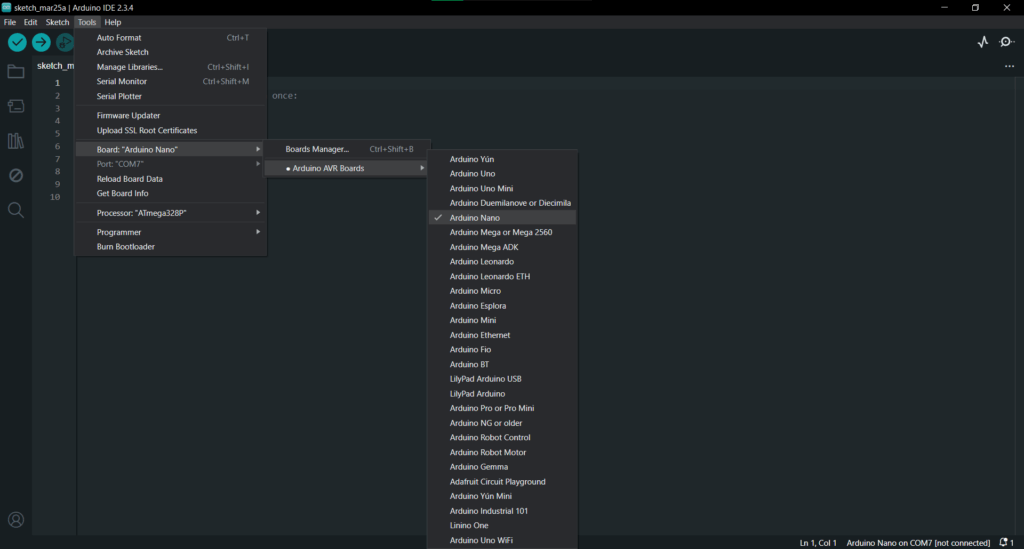
  • Connect your Arduino Nano to your computer via USB.Select the correct board: Tools > Board > Arduino Nano.
Fig: Selecting Board from Tools
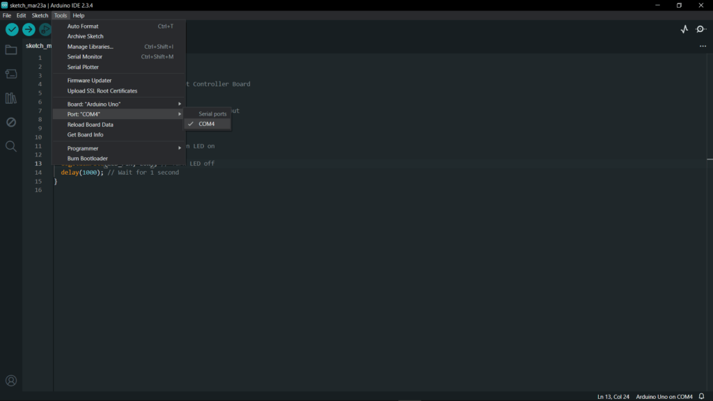
  • Select the correct port: Tools > Port > (your Arduino port).
Fig: Selecting Port
  • Copy and paste the above code into the Arduino IDE.
Fig: Copy and Pasting LED Code
  • Click on the Upload button or alternatively press Ctrl + U.
Fig: Clicking on Upload Button on Top-Left corner or by pressing Ctrl + U
  • Once uploaded, the LED should start blinking every second.
Fig: LED Starts Blinking

Conclusion

Blinking an LED is the first step in learning Arduino programming. Understanding pinMode(), digitalWrite(), and delay() functions helps build the foundation for more complex projects. You can now try modifying the blink interval or controlling multiple LEDs for advanced experimentation.

Shopping Cart